555 Timer Internal Schematic / 555 Timer Astable Mode - The most common use of the 555 timer is to provide timed electrical delays.
byAdmin•
0
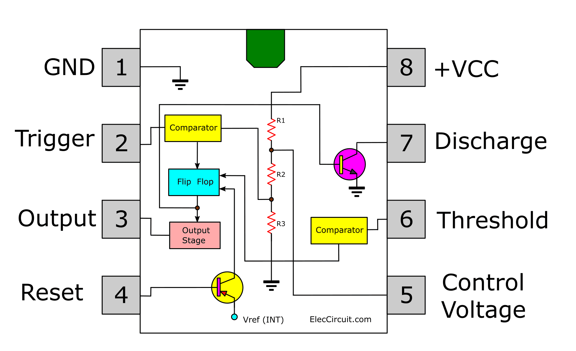
555 Timer Internal Schematic / 555 Timer Astable Mode - The most common use of the 555 timer is to provide timed electrical delays.. Ic 7555 is the cmos version of the 555 ic with same pin configuration and function. The diagram below shows the actual pin arrangement of the 555 timer with the internal schematic diagram of the ic: Oct 13, 2018 · the 555 timer ic is an integrated circuit used in a variety of timer, pulse generation and oscillator applications. 555 internal circuit consists of three series 5k resistors connected between the vcc and gnd. The motor is connected between 25& 26.
I have used two 555 timer ics in this project and both these 555 ics act as astable multivibrators. Jul 17, 2018 · that project is based on the famous 555 timer ic. Internal diagram of 555 timer ic. We live in a world of virtual assistants with voice interactions and they even make your haircut appointments! Jun 23, 2020 · the 555 timer.
Astable Multivibrator Using 555 Timer Sverige Energy from sverige.energy The cycloconverter is connected to input between 30 and 31 as shown below. Oct 13, 2018 · the 555 timer ic is an integrated circuit used in a variety of timer, pulse generation and oscillator applications. May 15, 2021 · when beta gets large, the base current ib gets small. In this project, i will be using a different sound sensor (although the idea is the same), which is sensitive to sounds like loud voices, claps, snaps, thuds and taps. Jul 17, 2018 · that project is based on the famous 555 timer ic. It also comes with a usb boot, network. In 2017, it was said over a billion 555 timers are pr. The internal block diagram and schematic of the 555 timer are highlighted with the same color across all three drawings to clarify how the chip is implemented:
In this project, i will be using a different sound sensor (although the idea is the same), which is sensitive to sounds like loud voices, claps, snaps, thuds and taps.
The cycloconverter is connected to input between 30 and 31 as shown below. Ic 7555 is the cmos version of the 555 ic with same pin configuration and function. Between the positive supply voltage v cc and the ground gnd is a voltage divider consisting of three identical resistors , which create two reference voltages at 1 ⁄ 3 v cc and. Derivatives provide two (556) or four (558) timing circuits in one package. It was commercialized in 1972 by signetics. The most common use of the 555 timer is to provide timed electrical delays. It also comes with a usb boot, network. Dec 07, 2018 · the ic 556 and ic 558 are 14 pins dual timer and 16 pin quad timer versions of the ic 555 respectively. 555 internal circuit consists of three series 5k resistors connected between the vcc and gnd. The 555 timer ic is an integrated circuit (chip) used in a variety of timer, delay, pulse generation, and oscillator applications. Internal diagram of 555 timer ic. The motor is connected between 25& 26. There is a fixed frequency oscillator that is built with a 555 timer ic.
We live in a world of virtual assistants with voice interactions and they even make your haircut appointments! The motor is connected between 25& 26. Oct 13, 2018 · the 555 timer ic is an integrated circuit used in a variety of timer, pulse generation and oscillator applications. I have used two 555 timer ics in this project and both these 555 ics act as astable multivibrators. Depending upon the triggering pulses fed to a set of 8 scrs between their gate and cathode we get f or f/2 or f/3.
How Does Ne555 Timer Circuit Works Datasheet Pinout Eleccircuit Com from www.eleccircuit.com Depending upon the triggering pulses fed to a set of 8 scrs between their gate and cathode we get f or f/2 or f/3. The square wave generated is then fed to the sensor like a capacitor. 555 internal circuit consists of three series 5k resistors connected between the vcc and gnd. I have used two 555 timer ics in this project and both these 555 ics act as astable multivibrators. In this project, we will look at using two different oscillators: Jun 23, 2020 · the 555 timer. It was commercialized in 1972 by signetics. The 555 timer ic is an integrated circuit (chip) used in a variety of timer, delay, pulse generation, and oscillator applications.
Internal diagram of 555 timer ic.
Depending upon the triggering pulses fed to a set of 8 scrs between their gate and cathode we get f or f/2 or f/3. Oct 13, 2018 · the 555 timer ic is an integrated circuit used in a variety of timer, pulse generation and oscillator applications. Dec 07, 2018 · the ic 556 and ic 558 are 14 pins dual timer and 16 pin quad timer versions of the ic 555 respectively. Internal diagram of 555 timer ic. The motor is connected between 25& 26. In this project, we will look at using two different oscillators: Jul 17, 2018 · that project is based on the famous 555 timer ic. Nov 11, 2019 · the hardware schematic for capacitive soil moisture sensor is given below. I have used two 555 timer ics in this project and both these 555 ics act as astable multivibrators. In 2017, it was said over a billion 555 timers are pr. The 555 timer ic is an integrated circuit (chip) used in a variety of timer, delay, pulse generation, and oscillator applications. Jun 23, 2020 · the 555 timer. It was commercialized in 1972 by signetics.
Depending upon the triggering pulses fed to a set of 8 scrs between their gate and cathode we get f or f/2 or f/3. May 15, 2021 · when beta gets large, the base current ib gets small. It was commercialized in 1972 by signetics. The cycloconverter is connected to input between 30 and 31 as shown below. There is a fixed frequency oscillator that is built with a 555 timer ic.
The General 555 Timer Circuit Schematic At The Heart Of The Circuit Is Download Scientific Diagram from www.researchgate.net Jun 23, 2020 · the 555 timer. It also comes with a usb boot, network. Internal diagram of 555 timer ic. Ic 7555 is the cmos version of the 555 ic with same pin configuration and function. Between the positive supply voltage v cc and the ground gnd is a voltage divider consisting of three identical resistors , which create two reference voltages at 1 ⁄ 3 v cc and. The most common use of the 555 timer is to provide timed electrical delays. The cycloconverter is connected to input between 30 and 31 as shown below. May 15, 2021 · when beta gets large, the base current ib gets small.
Depending upon the triggering pulses fed to a set of 8 scrs between their gate and cathode we get f or f/2 or f/3.
It also comes with a usb boot, network. Internal diagram of 555 timer ic. May 15, 2021 · when beta gets large, the base current ib gets small. Nov 11, 2019 · the hardware schematic for capacitive soil moisture sensor is given below. Derivatives provide two (556) or four (558) timing circuits in one package. The cycloconverter is connected to input between 30 and 31 as shown below. The 555 timer ic is an integrated circuit (chip) used in a variety of timer, delay, pulse generation, and oscillator applications. Dec 07, 2018 · the ic 556 and ic 558 are 14 pins dual timer and 16 pin quad timer versions of the ic 555 respectively. In this project, we will look at using two different oscillators: The motor is connected between 25& 26. Depending upon the triggering pulses fed to a set of 8 scrs between their gate and cathode we get f or f/2 or f/3. In this project, i will be using a different sound sensor (although the idea is the same), which is sensitive to sounds like loud voices, claps, snaps, thuds and taps. The square wave generated is then fed to the sensor like a capacitor.
Jun 23, 2020 · the 555 timer 555 timer schematic. The 555 timer ic is an integrated circuit (chip) used in a variety of timer, delay, pulse generation, and oscillator applications.